Revista Industrial Data
26(2): 315-333 (2023)
DOI: https://doi.org/10.15381/idata.v26i2.24008
ISSN: 1560-9146
(Impreso) / ISSN: 1810-9993 (Electrónico)
Prototype Android Application for Electromechanical Dimensioning of
Glass Insulator Strings under IEC-60071 and IEC-60815 (2008) Standards
Fabrizio Armando Millan
Montalvo
Jose Andres Huamani Cornejo
Jose Raul Izquierdo Perez
Christian Edward Rosales Inga
Karla Edita Salazar
Tello
Systems
and Information Technology
Submitted:
17/11/2022 Accepted: 12/04/2023 Published: 20/12/2023
DOI:
https://doi.org/10.15381/idata.v26i2.24008.g20436
ABSTRACT
In this study, a new Android application was
developed to help users accurately determine the dimensioning
of a string insulator through the analysis of the evaluation of two methods
based on IEC-60071 and IEC-60815 (2008) standards. The first method uses equations
from IEC-60815-2 (2008), while the second method considers
parameters such as relative air density and pressure. To ensure reliability, both
methods are evaluated: the first through the creepage factor to determine if
the chosen profile is suitable, and the second through lightning and
switching critical flashover voltages to avoid insulator
flashover. Tests were carried out using data from real projects, and those
results were compared with the results obtained from the application. The
number of string insulators obtained from the tests was exactly the same as the
number obtained from the application, except in two cases. Of the three
evaluations, all cases complied satisfactorily with at least two tests.
Keywords: insulator, application, creepage distance, correction
factor, dimensioning.
INTRODUCTION
Transmission and distribution lines are the
means of transport for electrical energy. They are mechanically fastened to
insulator strings to prevent the structure from being energized. For this
reason, proper dimensioning of the string is required. However, the calculation
is challenging for both engineering students and designers on real projects, as
different environmental, mechanical, and regulatory factors are considered. In
addition, human error is possible. Therefore, it is necessary to incorporate all
these factors into an interface that allows direct dimensioning through data
entry and selection.
The objective of this study is to develop the
correct calculation sequence for suspension insulator strings and based on
that, create a prototype Android application to select suspended glass
insulator strings according to International Electrotechnical Commission
standard 60815 (IEC, 2008a, 2008b) and 60071-2 (IEC, 1996) in order to provide
a tool to the electrical engineering community that can be used anywhere to
size the insulator string and also verify if existing strings are adequate.
The contribution of this article to scientific
knowledge is to provide a tool that can be used by engineers in projects and by
students in their professional academic development through the comparison of
their calculations with the results of the application. This contribution is
novel because it is an easy-to-use Android application with results that verify
its reliability.
Calculation and Selection Method
The calculations for the dimensioning of the insulator string are
made so that they meet the necessary requirements for the correct operation of
the transmission line. According to Orellana and Poma (2014), the requirements
consist of having high dielectric strength to avoid flashovers between the
conductor and the support, as well as decreasing the creepage current between
the insulator and the support, even in unfavorable conditions due to weather.
The application flowchart (Figure 2) was structured based on
the development of mathematical expressions that make it possible to obtain
desired results from manually entered data and data selected from the database
extracted from the VERESCENCE (2019) and Sediver (2018) catalogs.
Electrical Calculation
Parameters affecting the electrical calculation
of the glass insulator string were considered. Therefore, the number of insulators obtained must support the
conditions given by the user. For this reason, there will be two calculation
methods. The first is based entirely on the updated IEC-60815-2 standard (IEC,
2008b). The second method determines the result considering pressure and
relative air density. It should be noted that both the first and the second
method will use the contamination levels shown in Table 1, where the creepage distance
according to each pollution level is presented.
Table 1.
Pollution Levels - Reference Unified Specific
Creepage Distance (RUSCD).
|
Pollution Level
|
Basic RUSCD (mm/kV)
|
|
Very light
|
22.0 mm/kV
|
|
Light
|
27.8 mm/kV
|
|
Medium
|
34.7 mm/kV
|
|
Heavy
|
43.3 mm/kV
|
|
Very heavy
|
53.7 mm/kV
|
Source: RUSCD pollution
level parameter based on the pollution severity of the area. (IEC, 2008b).
Method 1: Number of Insulators Based on Creepage and
Arcing Distance
In this method, the mathematical equations found in the updated
standard mentioned above will be shown. Also, the data to be entered in the
application will be shown.
A.
Creepage distance at maximum
operating voltage according to IEC-60815-2 standard (IEC, 2008b):
 (1)
(1)
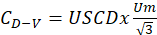
The mathematical expression of USCD is:
 (2)
(2)
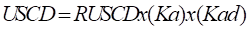
Now, from (1) and (2) the
following is obtained:
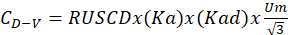 (3)
(3)
B. Altitude correction factor
Due to the influence of air pressure and density variation at
higher altitudes, which affects operating voltage, IEC-60815-2 standard (IEC,
2008b) mentions that an altitude correction factor must be applied, in
accordance with Díaz and Narváez (2015). This factor is shown in the following
equation (IEC-60071-2, 1996):
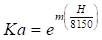 (4)
(4)
C.
Correction factor for insulator
average diameter
The IEC-60815-2 standard (IEC, 2008b) also considers a correction
factor based on the insulator diameter. In this sense, there are two conditions
defined by expressions (5) and (6).
 (5)
(5)
 (6)
(6)
D.
Number of insulators based on the
creepage distance
The following equation (7) considers the phase-to-earth creepage
distance, as specified in the IEC-60815-2 standard (IEC, 2008b). RUSCD only
considers phase-to-earth voltage, not line-to-line as in the previous version
of the standard.
 (7)
(7)
It is worth noting the
following:
 = Safety factor to avoid flashover in insulators
Number of insulators based on creepage distance
To obtain a complete mathematical expression, the equations
presented above will be joined. The correction factors  and
and  will be placed in expanded form, therefore two final equations are
displayed for the calculation of the number of insulators of method 1, which
will depend on the condition of the diameter of the insulator, therefore the
equations are as follows:
will be placed in expanded form, therefore two final equations are
displayed for the calculation of the number of insulators of method 1, which
will depend on the condition of the diameter of the insulator, therefore the
equations are as follows:
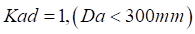
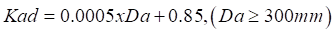
- If the diameter is less than 300 mm
 (8)
(8)
- If the diameter is greater than or equal to 300 mm
 (9)
(9)
It should be considered that will be greater than 1 when the
altitude is greater than 1000 m.a.s.l., otherwise, the value of the unit will
be considered.
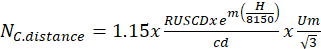
Equations (8) and (9) will be used in the application by entering
and selecting data, which are mentioned below.
Data to be selected:
-
 : Reference Unified Specific Creepage Distance (mm/kV)
-
 : 0.5 (normal), 0.8 (anti-fog)
or 1 (spherical or aerodynamic) according to IEC-60071-2 (1996)
: 0.5 (normal), 0.8 (anti-fog)
or 1 (spherical or aerodynamic) according to IEC-60071-2 (1996)
-  :
maximum operating voltage
:
maximum operating voltage
-  : creepage distance of the insulator (catalog)
-
 : average insulator diameter (nominal diameter if the insulator
does not have different diameters)
: average insulator diameter (nominal diameter if the insulator
does not have different diameters)
Data to enter:
-
 : height above sea level (m.a.s.l.)
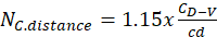
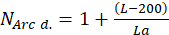
Number of insulators based on arcing distance
The choice of the number of insulators must be adequate so that
the length of the complete insulator string is greater or equal to the critical
phase-to-ground distance. In this sense, the calculation of the minimum number
of insulators is done using equation (10).
 (10)
(10)
While the vertical spacing “ ” is catalog data, “
 ” is the critical phase-to-earth distance that relates to the
IEC-60815-2 creepage factor (IEC, 2008b). This distance will be given by table
A-1 of IEC-60071-2 (1996).
” is the critical phase-to-earth distance that relates to the
IEC-60815-2 creepage factor (IEC, 2008b). This distance will be given by table
A-1 of IEC-60071-2 (1996).
Data to be selected:
: insulator vertical spacing (mm)
: critical phase-to-earth distance (mm)
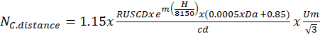
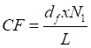
Evaluation of method 1 based on the creepage factor
In order to determine whether the choice of the insulator string
profile has been optimal, the present evaluation, based on the creepage factor,
is used and is calculated with the following equation (11):
 (11)
(11)
Where:
 : total nominal creepage distance of the insulator
 : arcing distance of the insulator (critical distance)
Although these variables are different from the ones used in the
previous equations, they have the same meaning:
 (12)
(12)
 (13)
(13)
 (14)
(14)
It should be noted that  is the number of insulators resulting from method 1.
The CF is useful to determine the suitability of the profile, as
shown in Figure 1, where the CF value must be kept in the white zone. If the CF
value moves to the gray or black zone, an insulator string with a different
profile is selected.
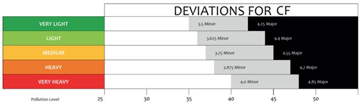
Figure 1. Deviations for the creepage
factor (CF) according to each pollution level.
Source: Adapted from Deviations for FC
from IEC 60815-1. (IEC, 2008a).
Method 2: Number of isolators by
pressure and relative air density
In this section, the calculation for the number of insulators will
be determined considering the relative air density (with pressure and
temperature), where A, B, and C are based on Portero (2019).
Equation (18) will be used in the application, where the data to
be entered and selected will be shown. In addition, the correction factors to
be used will be shown based on tables.
A. Barometric pressure
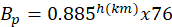 (cm/hg) (15)
B. Relative air density
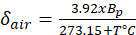 (16)
(16)
C. Number of insulators with maximum voltage ( )
)
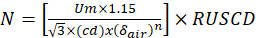 (17)
(17)
D. Precipitacion correction factor ( )
)
Table 2 shows a correction factor according to precipitation. This
correction factor is added to the equations in the form of multiplication.
Table 2.
Precipitation Correction Factor.
|
Rainfall Intensity
|
Correction Factor
|
|
0.00 mm/min
|
1.00
|
|
1.00 mm/min
|
0.95
|
|
1.27 mm/min
|
0.83
|
|
2.50 mm/min
|
0.77
|
|
3.80 mm/min
|
0.73
|
|
5.10 mm/min
|
0.71
|
|
6.30 mm/min
|
0.68
|
Source: Taken from
Cotto (2021).
E. Humidity correction factor ( )
)
Thedepends on the relative humidity and temperature. For a frequency
of 60hz, a double-entry table (Table 3) was made using two curve graphs to
obtain the value of the, which makes it an important database in the development of the application.
Table 3.
Humidity Correction Factor.
|
°C
|
Relative Humidity
|
|
10%
|
20%
|
30%
|
40%
|
50%
|
60%
|
70%
|
80%
|
90%
|
100%
|
|
0
|
1.14492694
|
1.14089224
|
1.11979946
|
1.12015942
|
1.11255994
|
1.10714298
|
1.09736524
|
1.09417581
|
1.08752743
|
1.07666906
|
|
1
|
1.14363001
|
1.13861078
|
1.11910865
|
1.1176695
|
1.10984326
|
1.10362938
|
1.09381732
|
1.08954026
|
1.08258559
|
1.07191786
|
|
2
|
1.14239911
|
1.13641712
|
1.11828013
|
1.11515852
|
1.10703346
|
1.10005624
|
1.09014831
|
1.08484951
|
1.07755023
|
1.06699671
|
|
3
|
1.14122649
|
1.13430128
|
1.11730835
|
1.11260943
|
1.10411497
|
1.0964082
|
1.08634458
|
1.0800814
|
1.07240115
|
1.06188822
|
|
4
|
1.14010448
|
1.13225343
|
1.11618792
|
1.1100055
|
1.10107265
|
1.09267041
|
1.08239315
|
1.07521476
|
1.06711926
|
1.0565763
|
|
5
|
1.13902548
|
1.13026391
|
1.1149136
|
1.10733036
|
1.09789186
|
1.08882854
|
1.07828165
|
1.07022945
|
1.06168665
|
1.05104624
|
|
6
|
1.13798196
|
1.12832319
|
1.11348036
|
1.10456801
|
1.09455847
|
1.0848688
|
1.07399846
|
1.06510644
|
1.0560866
|
1.04528481
|
|
7
|
1.13696643
|
1.12642187
|
1.11188335
|
1.10170284
|
1.09105893
|
1.08077819
|
1.0695327
|
1.05982785
|
1.05030405
|
1.03928037
|
|
8
|
1.13597148
|
1.1245507
|
1.11011794
|
1.09871966
|
1.0873803
|
1.07654408
|
1.06487433
|
1.05437706
|
1.04432492
|
1.033023
|
|
9
|
1.13498975
|
1.12270052
|
1.10817974
|
1.09560378
|
1.08351032
|
1.07215474
|
1.06001419
|
1.04873875
|
1.03813698
|
1.02650461
|
|
10
|
1.1340139
|
1.12086232
|
1.10606462
|
1.09234099
|
1.07943749
|
1.06759911
|
1.0549440
|
1.04289907
|
1.03172956
|
1.01971908
|
|
11
|
1.13303667
|
1.1190272
|
1.10376871
|
1.08891763
|
1.0751511
|
1.0628669
|
1.04965675
|
1.03684566
|
1.02509375
|
1.01266234
|
|
12
|
1.13205085
|
1.11718635
|
1.10128843
|
1.08532065
|
1.07064128
|
1.05794894
|
1.04414613
|
1.03056782
|
1.01822248
|
1.00533254
|
|
13
|
1.13104926
|
1.11533112
|
1.09862051
|
1.08153768
|
1.06589913
|
1.05283655
|
1.03840722
|
1.02405656
|
1.01111068
|
0.99773016
|
|
14
|
1.13002479
|
1.11345295
|
1.09576203
|
1.07755704
|
1.06091674
|
1.04752233
|
1.03243627
|
1.01730476
|
1.00375537
|
0.98985811
|
|
15
|
1.12897036
|
1.11154341
|
1.09271038
|
1.07336782
|
1.05568729
|
1.04199982
|
1.02623082
|
1.01030728
|
0.99615574
|
0.98172183
|
|
16
|
1.12787898
|
1.1095942
|
1.08946333
|
1.06895997
|
1.0502051
|
1.0362637
|
1.01978974
|
1.00306105
|
0.98831332
|
0.97332943
|
|
17
|
1.12674369
|
1.10759714
|
1.08601906
|
1.06432434
|
1.04446573
|
1.03030981
|
1.01311334
|
0.9955652
|
0.98023203
|
0.96469176
|
|
18
|
1.12555762
|
1.10554421
|
1.08237611
|
1.05945278
|
1.0384660
|
1.02413522
|
1.00620342
|
0.98782116
|
0.9719183
|
0.95582247
|
|
19
|
1.12431396
|
1.10342754
|
1.07853347
|
1.05433816
|
1.03220427
|
1.01773833
|
0.99906331
|
0.97983279
|
0.96338118
|
0.94673811
|
|
20
|
1.12300599
|
1.10123939
|
1.07449057
|
1.0489744
|
1.02568012
|
1.01111889
|
0.9916979
|
0.97160645
|
0.95463235
|
0.93745811
|
|
21
|
1.12162706
|
1.09897223
|
1.07024729
|
1.04335697
|
1.01889479
|
1.00427808
|
0.98411399
|
0.9631511
|
0.9456862
|
0.9280048
|
|
22
|
1.12017064
|
1.0966186
|
1.06580399
|
1.0374821
|
1.01185111
|
0.99721858
|
0.97631971
|
0.95447841
|
0.93656014
|
0.91840374
|
|
23
|
1.11863028
|
1.09417159
|
1.06116153
|
1.03134771
|
1.00455353
|
0.9899446
|
0.96832519
|
0.9456027
|
0.92727399
|
0.9086829
|
|
24
|
1.11699967
|
1.09162398
|
1.05632127
|
1.02495304
|
0.9970082
|
0.9824620
|
0.96014227
|
0.93654131
|
0.91785063
|
0.89887339
|
|
25
|
1.11527261
|
1.08896914
|
1.0512851
|
1.01829885
|
0.98922325
|
0.97477828
|
0.95178461
|
0.92731409
|
0.90831567
|
0.8890089
|
|
26
|
1.11344304
|
1.0862005
|
1.04605547
|
1.01138745
|
0.98120829
|
0.9669025
|
0.9432676
|
0.91794391
|
0.8986974
|
0.87912593
|
|
27
|
1.11150506
|
1.08331202
|
1.04063536
|
1.00422278
|
0.9729750
|
0.9588457
|
0.9346088
|
0.9084563
|
0.8890269
|
0.86926298
|
|
28
|
1.10945292
|
1.0802975
|
1.03502833
|
0.9968104
|
0.9645370
|
0.95062057
|
0.9258270
|
0.8988799
|
0.87933753
|
0.8594609
|
|
29
|
1.10728106
|
1.07715161
|
1.02923853
|
0.98915794
|
0.9559098
|
0.94224136
|
0.91694335
|
0.8892454
|
0.86966511
|
0.84976232
|
|
30
|
1.10498412
|
1.0738687
|
1.02327069
|
0.98127434
|
0.94711067
|
0.93372434
|
0.9079803
|
0.8795866
|
0.8600475
|
0.84021127
|
|
31
|
1.10255692
|
1.0704440
|
1.01713015
|
0.9731707
|
0.9381589
|
0.92508747
|
0.8989622
|
0.8699393
|
0.8505247
|
0.83085283
|
|
32
|
1.0999945
|
1.0668728
|
1.01082287
|
0.9648599
|
0.9290759
|
0.91635045
|
0.8899150
|
0.8603416
|
0.84113776
|
0.82173254
|
|
33
|
1.0972922
|
1.06315096
|
1.00435539
|
0.9563568
|
0.91988473
|
0.9075346
|
0.8808661
|
0.8508334
|
0.83192914
|
0.81289585
|
|
34
|
1.0944456
|
1.05927453
|
0.9977349
|
0.9476782
|
0.91061016
|
0.8986632
|
0.87184425
|
0.84145628
|
0.82294194
|
0.80438741
|
|
35
|
1.0914504
|
1.05524017
|
0.9909692
|
0.9388425
|
0.90127893
|
0.8897607
|
0.86287941
|
0.83225274
|
0.81421932
|
0.79625034
|
Source:
Adapted with AutoCAD and Excel from the “Dry Blub Temperature - °C” chart and
“Absolute Humidity – g/m3” charts of LaForest (1982).
Equation for the number of insulators based on
pressure and relative air density
Equation (18), which will be used in the app, allows finding the
number of insulators based on maximum voltage.
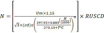 (18)
(18)
Where:
- Data to select:
-
 : maximum voltage in kV, according to IEC 60071-1 (IEC, 1993)
-
 : Reference Unified Specific Creepage Distance (mm/kV) –
IEC-60815-2 (IEC, 2008b)
: Reference Unified Specific Creepage Distance (mm/kV) –
IEC-60815-2 (IEC, 2008b)
- : creepage distance of the insulator (catalog)
-
 : If
: If  kV, n = 1; if
  kV, n = 0.9
- Data to enter:
-
 : ambient
temperature
: ambient
temperature
-
 : height above sea level (m.a.s.l.)
Evaluation of the number of
insulators based on switching critical flashover voltage (CFO switch.)
The number of insulators to be calculated in method 2 must be
adequate to withstand the switching critical
flashover voltage. For this calculation, the
following equation will be used, based on Mendoza et al. (2013), which
considers climatic factors such as rain and humidity.
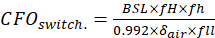 (19)
(19)
The altitude correction factor  , as well as
  , will be greater than 1 when the altitude is greater than 1000 m.a.s.l.
Otherwise, the value of the unit will be considered.
, will be greater than 1 when the altitude is greater than 1000 m.a.s.l.
Otherwise, the value of the unit will be considered.
For direct data entry as in the previous equations, the equation
will be defined as follows:
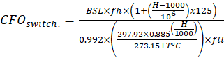 (20)
(20)
For equation (20), the
following will be considered:
- Data to be selected:
-
 : basic switching impulse insulation level, according to standard
IEC-60071-1 (IEC, 1993)
: basic switching impulse insulation level, according to standard
IEC-60071-1 (IEC, 1993)
-
 : humidity
correction factor
: humidity
correction factor
-
 : precipitation
correction factor
: precipitation
correction factor
- Data to be entered:
-
: height above sea level (m.a.s.l.)
-
 : ambient
temperature
: ambient
temperature
The switching critical flashover voltage must be less than the voltage that the insulator string will withstand.
Therefore, the following condition is proposed, which will be used for the
evaluation of method 2:

 (21)
(21)
Where the data to be selected will be:
 : withstand voltage at industrial frequency (catalog)
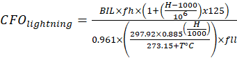
Evaluation of the number of insulators based on
lightning critical flashover voltage (CFO lightning).
In the same way as in the previous evaluation, the following
equation based on Mendoza et al. (2013) will be used. This equation will also
consider climatic factors.
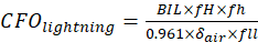 (22)
(22)
The altitude correction factor , as well as
  , will be greater than 1 when the altitude is greater than 1000
m.a.s.l. Otherwise, the value of the unit will be considered.
, will be greater than 1 when the altitude is greater than 1000
m.a.s.l. Otherwise, the value of the unit will be considered.
For direct data entry as in the previous equations, the equation
will be defined as follows:
 (23)
(23)
For equation (23), the
following will be considered:
- Data to be selected:
-
 : basic impulse insulation
level, which is the lightning impulse voltage according
to standard IEC-60071-1 (IEC, 1993)
: basic impulse insulation
level, which is the lightning impulse voltage according
to standard IEC-60071-1 (IEC, 1993)
-
 : humidity
correction factor
: humidity
correction factor
-
: precipitation
correction factor
- Data to be entered:
-
: height above sea level (m.a.s.l.)
-
 : ambient
temperature
: ambient
temperature
The lightning critical
flashover voltage must be less than the
voltage that the insulator string will withstand. Therefore, the following
condition is proposed, which will be used for the evaluation of method 2:
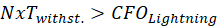 (24)
(24)
Where the data to be selected will be:
 : withstand voltage at industrial frequency (catalog)
Resulting number of insulators
Based on the previous results, the resulting number of insulators
will be the largest of the three numbers obtained, which have had to pass the
evaluations shown, mathematically the final result can be expressed as follows.

 (25)
(25)
 (26)
(26)
 (27)
(27)
Where:
 : number of insulators resulting from the calculation
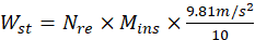
Mechanical calculation
For the mechanical calculation, the equations used by the
application to calculate and select insulators, based on López (2018) and De la
Fuente (2016), will be shown. Therefore, the accessory that mechanically joins
the insulators with the transmission lines,
called a fitting, must be taken into account. The weight of the insulator
string and the fittings will be calculated
through the following ratio:
 (28)
(28)
 (29)
(29)
Where:
-
Wst: string weight (daN)
-
Nre: number of
insulators in the resulting string
-
Wst+F: Weight of the
insulator string plus fitting (daN)
- Data to be selected:
-
Mins: mass of an
insulator (kg)
- Data to be entered:
-
WFitting: fitting weight (daN)
For the mechanical calculation, the factor of safety for failure
of glass insulators Fos must be greater than 3. The insulator must withstand
the normal loads acting on it.

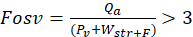 (30)
(30)
Where:
-
Fosv: factor of safety for failure
of insulators under normal loads
- Data to be selected:
-
Qa: breaking load of the
insulator (daN)
- Data to be entered:
-
Pv: vertical stress
transmitted by the conductors to the insulator (daN)
Likewise, the insulator withstands abnormal loads that are found
by means of the following expression:
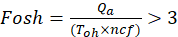 (31)
(31)
Where:
-
Fosh: factor of safety for failure
of insulators under abnormal loads
- Data to be selected:
-
Qa: failing load of the
insulator (daN)
- Data to be entered:
-
Toh: maximum horizontal
tension under the most unfavorable conditions (daN)
-
ncf: number of
conductors per phase (daN)
Following this, the string length will be calculated with the
following expression:
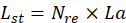 (32)
(32)
Where:
-
Lst: string length
(mm)
-
Nre: number of
insulators of the resulting string (number obtained from calculations)
-
La: length of insulator or
spacing (mm)
Finally, it gives the following expression for the wind
stress generated on the insulator string:
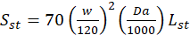 (33)
(33)
Where:
-
Sst: wind stress on
the insulator string (daN)
-
Lst: length of
string (mm)
Data to be selected:
-
Da: maximum
diameter of the insulator (mm)
Data to be entered:
-
W: wind speed (Km/h)
Selecting the insulator profile
The considerations on the items 9.1. 9.2 and 9.3 of the standard
IEC-60815-1 (IEC, 2008a) must be taken into account when selecting the
insulator profile. The profiles are the following:
Standard: Used in lines
whose pollution is light or medium.
Anti-fog: Used in areas with
medium to heavy pollution.
Spherical: Similar to an open or aerodynamic profile.
Open or aerodynamic: It has a flat area, which is
very useful in desert areas since the wind cleans the surface of the insulator.
Testing the app
To determine the reliability of the application based on a real
situation, different data extracted from calculation memories of real and
completed projects will be used as a reference, as shown in Table 4. The table
also shows the number of insulators resulting from these calculation memories.
Table 4. Data from
Real Projects.
|
TESTS
|
1
|
2
|
3
|
4
|
5
|
6
|
|
Transmission Line 500 kV
La Niña – Piura Nueva
|
Transmission Line 2 x 220
kV Piura Nueva – Piura Oeste
|
Sub-Station Friaspata
|
Sub-transmission
line to 69 kV Songa
|
Transmission
Line 220 kV Reus – Tarragona
|
Transmission Line 220 kV
Reque – Nueva Carhuaquero
|
|
T (°C)
|
30
|
30
|
16
|
20
|
-
|
-
|
|
Relative humidity (%)
|
75
|
75
|
80
|
80
|
-
|
-
|
|
m.a.s.l.
|
39
|
39
|
3730
|
6
|
-
|
-
|
|
BIL (kV)
|
1550
|
1050
|
1300
|
325
|
1050
|
1050
|
|
BSL (kV)
|
1175
|
460
|
460
|
140
|
460
|
460
|
|
Umax (kV)
|
550
|
245
|
245
|
72.5
|
245
|
245
|
|
Spacing (mm)
|
159
|
146
|
146
|
146
|
170
|
146
|
|
Diameter (mm)
|
330
|
330
|
280
|
254
|
320
|
280
|
|
Creepage distance (mm)
|
620
|
545
|
445
|
290
|
530
|
445
|
|
Pollution level
|
Heavy
|
Heavy
|
Heavy
|
Heavy
|
Very heavy
|
Very heavy
|
|
Number of insulators (calculation memory)
|
28
|
14
|
23
|
5
|
15
|
18
|
Source: Data extracted
from Comité de Operación Económica del Sistema Interconectado Nacional (COES,
2016a, 2016b), SIEMENS (2016), Orellana and
Cevallos (2019), COES (2018), and Olives (2016).
Hypotheses
1.
The resulting number of
insulators coincides in at least 90% with the results of the calculation
memories.
2.
At least two out of the three evaluations of the
calculation methods will result in the term “Acceptable” that will be shown in
the app.
METHODOLOGY
Objective and Justification
This work was carried out with the objective of
optimizing the dimensioning of glass insulator strings by means of a prototype
of an Android application with a didactic interface for academic and
professional use. The choice of an application is based on the practicality it
offers, since users can download it and access it from their cell phones.
Initially, the development of the calculation was made in Excel, however, the
scope of the prototype is greater if it is used on a cellphone, which functions
as a computer, which greatly increases its accessibility.
Development
The development of the app was based on the standards
mentioned before and environmental factors were taken into consideration. For
this reason, two calculation methods that complemented each other were
developed to give a better result. The calculation evaluations were developed
together and fulfill the objective of providing knowledge about the
acceptability of the type of insulator and its characteristics.
Obtaining the Table “Humidity Correction Factor”
AutoCAD and Excel were used to approximate two
tables in order to obtain the humidity correction factor. In this way it was
possible to obtain the curves of the tables and create a double-entry table to
find the humidity correction factor. This value is extracted from crossing the
relative humidity row and the temperature column of Table 3.
Order of the Calculation Process
Once the calculation base was obtained, the
flowchart shown in Figure 2 was developed. This flowchart is the visual
representation of the operation made by the Android app, which was developed
with a database uploaded to the cloud. Finally, the product obtained is an
application that generates a report of the calculations.
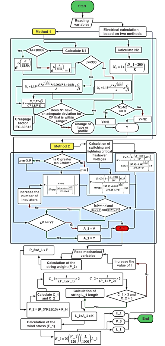
Figure 2. Flowchart for the application.
Source: Prepared by the authors using Lucid.app.
The flowchart shown contains input and output
variables that can be seen in Table 5, where the meaning of each variable can
be found.
Table 5. Variables
Declared on the Flowchart.
|
Input and Output Variables
|
Variables’ Meaning
|
|
A
|
Altitude (m.a.s.l.)
|
|
B
|
Temperature (°C)
|
|
C
|
Maximum voltage (kV)
|
|
D
|
Basic insulation level (kV)
|
|
D_1
|
Critical
distance (mm)
|
|
E
|
Basic switching impulse insulation level (kV)
|
|
F
|
Pollution
level (mm/kV)
|
|
N_1
|
Number of conductors per phase
|
|
T_1
|
Maximum
horizontal tension (daN)
|
|
G
|
Profile or type of insulator
|
|
H
|
Insulator
code
|
|
I
|
Failing
load (daN)
|
|
J
|
Creepage
distance (mm)
|
|
K
|
Spacing
(mm)
|
|
L
|
Diameter
(mm)
|
|
M
|
FT-dry (kV)
|
|
N
|
FT-precipitation (kV)
|
|
O
|
FT-lightning (kV)
|
|
P
|
Insulator
mass (kg)
|
|
Q
|
Relative
humidity
|
|
R
|
Precipitation
correction factor
|
|
P_H
|
Fitting
weight (daN)
|
|
Z
|
Humidity
correction factor
|
|
C_1
|
Safety coefficient to the breakage of the insulators with abnormal
loads.
|
|
P_1
|
Factor of safety for failure of insulators under abnormal loads (daN)
|
|
T_1
|
Maximum
horizontal tension (daN)
|
|
P_2
|
Weight of the insulator string and fitting (daN)
|
|
C_2
|
Factor of safety for failure of insulators under normal loads (daN)
|
|
L_1
|
Length of insulator string (mm)
|
|
P_3
|
Mass of the insulator string (kg)
|
|
E_1
|
Wind stress on the string (daN)
|
|
V_1
|
Wind speed
(km/h)
|
Source: Prepared by
the authors.
App Development and User Interface
The Android application was developed in Java
language using Android default libraries and control structures, which are
mostly conditional and loops. In this way the equations were placed and
connected following the structure of Figure 2. In addition, the database
containing tables and insulator data was uploaded to the cloud using the platform
Firebase.
The equations previously shown for the dimensioning of the
insulator string will be entered into the application together with the
database containing the necessary parameters for the selection. Figures 3, 4,
5, 6 and 7 show the user interface where the data will be entered and selected
in the application. This will be done in each of the fields shown, which have
boxes, drop-down lists and buttons for easy use. The name of the application
will be “Untels Insulator”.
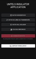
Figure 3. Main User Interface.
Source: Prepared by
the authors (screenshot).
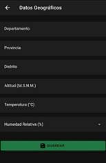
Figure 4. User Interface for Geographic Data.
Source: Prepared by
the authors (screenshot).
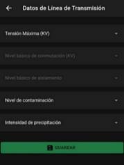
Figure 5. User
Interface for Transmission Line Data.
Source: Prepared by
the authors (screenshot).
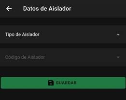
Figure 6. User
Interface for Insulator Data.
Source: Prepared by
the authors (screenshot).
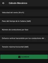
Figure 7. User Interface for Mechanical Calculation.
Source: Prepared by
the authors (screenshot).
Limitations of the Application Prototype
During the development and implementation of the
application, certain limitations were found. These are mainly related to the
database since there are only two glass insulator catalogs. Also, an option for
manual data entry has not yet been developed since it considerably increases
the complexity of the programming. It is worth mentioning that the application
is also limited only to glass insulators and does not cover those made of
polymers.
RESULTS
To verify the correct functioning of the
application, actual data were taken from Table 4. These data were entered into
the application following the order of the user interface in each of its four
sections of data to be entered and selected. Finally, a report was generated
with each case presented in Table 4.
Tests 1, 2 and 4 considered “anti-pollution” or
“anti-fog” profile insulators based on “heavy” pollution level and the
insulator characteristics shown in Table 4. The insulator model chosen for the
tests has very similar characteristics to the ones shown in the table, since
the same model is not found in the database. It is worth mentioning that the
insulator model with the same characteristics was applied in test 3 since it is
in the database.
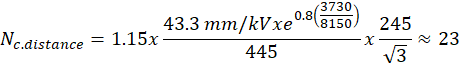
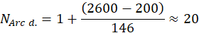
Case 3 calculation:
The manual calculation process will be done using
the data of case 3.
Method 1:
Method 2:
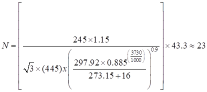
With both methods, the number of insulators is
23.
Evaluation of method 1:
Equation 14 is used considering the data of case
3 finding that:
CF = 3.53
This result is contrasted with Figure 1 and is
observed to be within limits.
Evaluation of method 2:
It is evaluated with equations 21 and 24, so that:
Switch critical flashover voltage evaluation (equations 20 and 21)
As the withstand voltage of the string at the
switch critical flashover voltage (1150 kV) is higher
than that calculated in the phase, it will be considered
as an acceptable evaluation.
Lightning critical flashover voltage evaluation (equations 23 and 24)
As the withstand voltage of the string in lightning
critical flashover voltage (2875 kV) is lower than that calculated in the phase, it will be considered as an
unacceptable evaluation.
Note: This process is performed with the data
required in the equations and within the application. The results of all cases
are shown in Figures 8, 9, 10 and 11 through screenshots taken during the
tests.
Figure 8. Results
of Test 1.
Source: Prepared by
the authors (screenshot).
Figure 9. Results of Test 2.
Source: Prepared by
the author (screenshot).
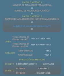
Figure 10. Results of Test 3
Source: Prepared by
the authors (screenshot).

Figure 11. Results
of Test 4.
Source: Prepared by
the authors (screenshot).
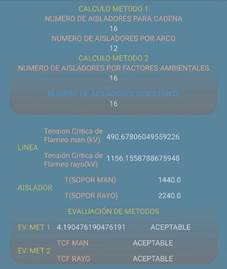
Figure 12. Results of Test 5.
Source: Prepared by
the authors (screenshot).
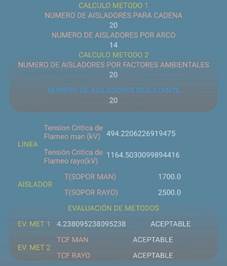
Figure 13. Results of Test 6.
Source: Prepared by
the authors (screenshot).
The contrast of results is shown in Table 6,
where it is possible to appreciate both the results obtained by the application
according to the number of resulting insulators, and the result of the
evaluations of the methods described above. From this it can be seen that tests
1, 2, 3 and 4 have 100% certainty and tests 5 and 6 have 93.75% and 90%
respectively, which shows that hypothesis 1 is correct.
For hypothesis 2, the range of acceptability is
above 66%. It means that at least two of the three evaluations of the
calculation method have the term “Acceptable”, which validates the hypothesis.
Table 6. Contrast of
results according to calculation memories and those obtained from the application.
|
TESTS
|
1
|
2
|
3
|
4
|
5
|
6
|
|
Transmission Line 500 kV La Niña – Piura Nueva
|
Transmission Line 2 x 220 kV Piura Nueva – Piura Oeste
|
Sub-Station Friaspata
|
Design and Construction of Sub-transmission
line to 69 kV Songa
|
Transmission
Line 220 kV Reus – Tarragona
|
Transmission Line 220 kV Reque – Nueva Carhuaquero
|
|
Number of insulators (calculation memory)
|
28
|
14
|
23
|
5
|
15
|
18
|
|
Number of insulators (application)
|
28
|
14
|
23
|
5
|
16
|
20
|
|
Percentage of closeness to actual results
|
100%
|
100%
|
100%
|
100%
|
93.75%
|
90%
|
|
Creepage factor evaluation
|
Non acceptable
|
Acceptable
|
Acceptable
|
Acceptable
|
Acceptable
|
Acceptable
|
|
CFO switching Evaluation
|
Acceptable
|
Acceptable
|
Acceptable
|
Acceptable
|
Acceptable
|
Acceptable
|
|
CFO lightning Evaluation
|
Acceptable
|
Acceptable
|
Non acceptable
|
Acceptable
|
Acceptable
|
Acceptable
|
|
Acceptability percentage of results
|
66%
|
100%
|
66%
|
100%
|
100%
|
100%
|
Source: Prepared by
the authors.
DISCUSSION
The results of the application presented in
Table 6 exactly coincide with COES (2016a, 2016b), SIEMENS (2016) and Orellana
and Cevallos (2019), whose calculations are based on actual projects. However,
the results of the application disagree with tests 5 and 6. Likewise, in the
evaluations of the calculations, it is highlighted that tests 2, 4, 5 and 6
show results termed “Acceptable” in the three evaluations. However, test 1
failed in the evaluation of the creepage factor, which determines that the
profile of the anti-pollution insulator is not acceptable. Likewise, test 3
failed in the evaluation of the lightning critical flashover voltage, therefore
the lightning withstand is not adequate. In this regard, it should be
emphasized that the limitation of the application is not being able to enter
the data of a new insulator, since, for this reason, in tests 2 and 4,
insulators with very similar characteristics had to be used. This does not mean
that the calculated string does not work, but that changes in the insulator
model can and should be made to obtain a better response from the evaluation of
calculation methods.
CONCLUSIONS
The calculation optimization through the
prototype application shown in this study meets the proposed objective, which was
to optimize the dimensioning of glass insulator strings by means of a prototype
application. In addition, the two hypotheses proposed were demonstrated and
validated through the tests performed using real data from transmission line
projects, where the results obtained from the application were mostly totally
satisfactory. In addition, the practical use of the application makes it a very
interesting and didactic tool with a great potential for the user, who only
needs their cell phone to perform the dimensioning. In this way, the objective
of easy accessibility and correct dimensioning is achieved.
ACKNOWLEDGMENT
To God, for granting us the sense and wisdom to
overcome every obstacle that we encountered during the development of this study.
To our families and colleagues, for their
unwavering support when problems arose. Thank you for giving us your moral and financial
support throughout our professional journey. Without your support, we would not
have been able to complete this study.
To professor Millán Montalvo, for his constant
encouragement, guidance, and knowledge that were instrumental in the completion
of this research study.
REFERENCES
[1]
Comité de Operación Económica del Sistema Interconectado
Nacional. (2016a). Enlace 500 kV La Niña - Piura, Subestaciones, Líneas y
ampliaciones asociadas - PARTE I.
[2]
Comité de Operación Económica del Sistema Interconectado
Nacional. (2016b). Enlace 500 KV La Niña - Piura, Subestaciones, Líneas y
ampliaciones asociadas - PARTE II.
[3]
Comité de Operación Económica del Sistema Interconectado Nacional. (2018). Anteproyecto «Línea de
transmisión de 220 kV Reque - Nueva Carhuaquero y subestaciones asociadas».
Pepsa Tecsult. https://www.minem.gob.pe/minem/archivos/Enlace%20220%20kV%20Reque%20Nueva%20Carhuaquero.pdf
[4]
Cotto Macul, Z. Y. (2021). Análisis
del nivel de aislamiento utilizados en sistemas de distribución y
subtransmisión aéreas mediante el software ATP-DRAW. (Degree project).
Universidad Politécnica Salesiana, Guayaquil.
[5]
De la Fuente, M. (2016). Modificación
de línea aérea de alta tensión por cambio de conductor y de tensión. (Final degree project). Universidad de Valladolid,
Valladolid. https://uvadoc.uva.es/bitstream/handle/10324/17055/TFG-P-356.pdf?sequence=1&isAllowed=y
[6]
Díaz Sierra, H. R., & Narváez
Gómez, R. O. (2015). Evaluación para la
coordinación de aislamiento y distancias eléctricas en subestaciones de 220 Kv
y 500 Kv en altitudes entre 2.500 y 5.500 m.s.n.m. (Degree project). Universidad Pontificia Bolivariana,
Medellín. https://repository.upb.edu.co/handle/20.500.11912/2431
[7]
International
Electrotechnical Commission. (1993). Insulation co-ordination. Part 1: Definitions, principles and rules (IEC
60071-1:1993).
[8]
International
Electrotechnical Commission. (1996). Insulation co-ordination. Part 2:
Application guide (IEC
60071-2:1996).
[9]
International
Electrotechnical Commission. (2008a). Selection and Dimensioning of
High-Voltage Insulators Intended for use in Polluted
Conditions. Part 1: Definitions Information and General Principles (IEC/TS 60815-1:2008).
https://webstore.iec.ch/publication/3573
[10] International Electrotechnical Commission. (2008b). Selection and Dimensioning of High-Voltage Insulators
Intended for use in Polluted Conditions. Part 2: Ceramic and Glass Insulators
for A.C. Systems (IEC/TS 60815-2:2008). https://webstore.iec.ch/publication/3574
[11] LaForest, J. (1982). Transmission Line
Reference Book. 345 kV and Above/Second Edition. Palo Alto, CA, USA:
Electric Power Research Institute.
[12] López Salazar, J. P. (2018). Instalación Eléctrica De
MT, Centro De Transformación Y Red De BT En El Polígono Industrial De Valverde
Del Fresno (Caceres). https://contrataciondelestado.es/wps/wcm/connect/717ffde5-7146-43ee-badb-980b9c905502/DOC20181001110905Proyecto+final+Valverde+del+Fresno.pdf?MOD=AJPERES
[13] Mendoza Jasso, C., Rocha Lerma, P. F., &
Santiago Bautista, H. (2013). Diseño de la Coordinación
de Aislamiento para una Línea de Transmisión Compacta de 230KV. (Tesis de grado). Instituto Politécnico Nacional, México
D. F.
[14] Olives Piris, R. (2016). Línea de
transporte de energía eléctrica de 220 kV y 200 MVA. (Trabajo de fin de
grado). Universidad Politécnica de Cataluña.
[15] Orellana Riofrio, D. I., & Poma Quinche, J. C. (2014). Fabricación
a nivel de laboratorio del aislador eléctrico de cerámica tipo ANSI 53-2 y sus
respectivos bastidores para sujeción en mampostería. (Degree project).
Escuela Politécnica Nacional, Quito.
[16] Orellana Ochoa, W. W., & Cevallos Álvarez, L. G. (2019).
Diseño Construcción de la línea de Subtransmisión a 69KV Songa. (Degree
project). Universidad Politécnica Salesiana, Guayaquil.
[17] Portero Calderón, R. P. (2019). Coordinación óptima de
aislamiento en líneas de transmisión de alto voltaje considerando restricciones
de contaminación. (Degree project). Universidad Politécnica Salesiana Sede
Quito, Quito.
[18] Sediver. (2018). Sediver®
toughened glass insulators for HVAC applications. https://www.sediver.com/wp-content/uploads/C28-2018_Canada.pdf
[19] SIEMENS.
(2016). Memoria de cálculo selección de cadenas de aisladores (SA-REP,
PE-FRMO-GP015).
[20] VERESCENCE. (2019). Aisladores
de Vidrio. LaGranjaInsulators. https://studylib.net/doc/25849106/03-full-catalogue-lagranjainsulators-es-en-2019-low